Now it is time to gather up all the wood boards and the acrylic sheet to take the CNC vendor for cutting. The CNC machine will make sure that all our cuts for the button, joystick, and other device holes were exact.
In the previous post, we cut the MDO plywood into a number of rectangular boards of various sizes. We left extra space around the outside of where each of the boards will be cut using the CNC machine so that there was plenty of room for the wood to be secured during the cutting operations.
Selecting a Vendor
I had done some research on vendors within a certain mile radius who would be able to work with us on cutting the plywood pieces and acrylic. There weren’t many appealing options, but I did come across a newer company named The Maker Lab that wasn’t located too far away and seemed to have all the equipment necessary to do the cuts for this project.
I reached out to them and the two guys running it (Nick and Jason) were very responsive. We discussed what was needed on their end and since this was my first time working with a CNC vendor, they gave me hints on how to approach everything. I settled on using them and started preparing the plans for the cuts.
Planning the Cuts
There were a lot of plywood pieces that needed exact cuts for holes and routings in some cases. I put together a very detailed document (partially displayed below) that gives each plywood piece a number and full description.
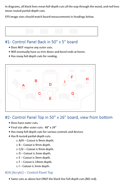
The control panel top involved many full-depth hole cutouts. It also required several other routed cuts that didn’t go all the way through the plywood piece. These were labels clearly with letters and the description told them how deep those routings needed to be.
For instance, joysticks needed to be routed 9mm deep so that the joystick ball and shaft could be at a proper height once mounted. The trackball we purchased was made to be mounted flush in a 3/4” wood board, but since we are also placing a 3mm acrylic sheet on top of it, we had to route the trackball area out by 3mm to retain the flush mount.
The 7” display in the middle of the control panel was made to be mounted in a thinner material, and needed additional area where cords could run out from its sides. It also needed some routing above it so that top-mounted buttons, which will be on the underside of the control panel, could be pressed.
Submitting Plans and Files
I sent The Maker Lab the plans, along with SVG exports of all vector drawings I made using Affinity Designer for each of the plywood boards. This allowed them to build tool path renderings that they sent back to me for verification.
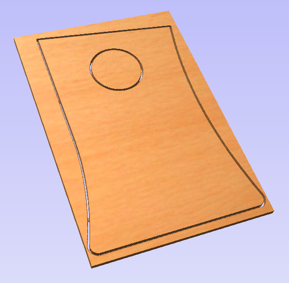
This is a tool path rendering of the two side plywood pieces. It shows the outer cuts and the hole that will be created for the fan.
Packing Up the Car
Since our work order had nine plywood pieces involved, it was important to label them all properly to match the submitted plans. We wrote a number and description on each plywood piece in pencil so that they could easily be matched up with the plans that were previously submitted.
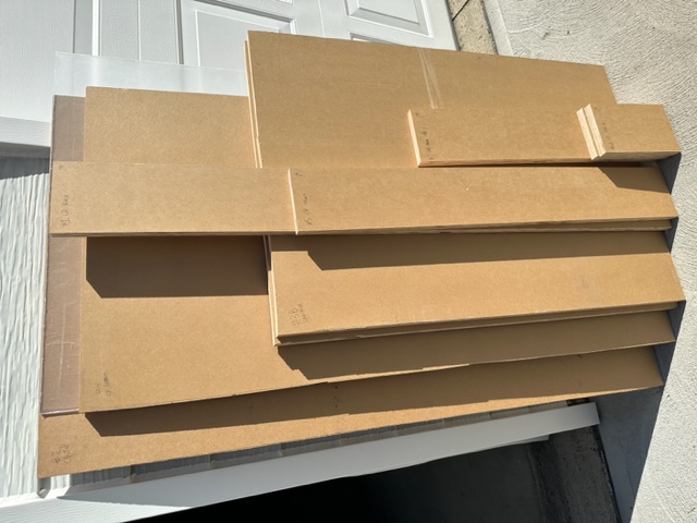
Next, we packed up the car with all the plywood pieces and acrylic sheet.
At the CNC Vendor
When we got to The Maker Lab, we unloaded the materials and sat down with Nick. He walked us through all the cuts in detail on his computer.
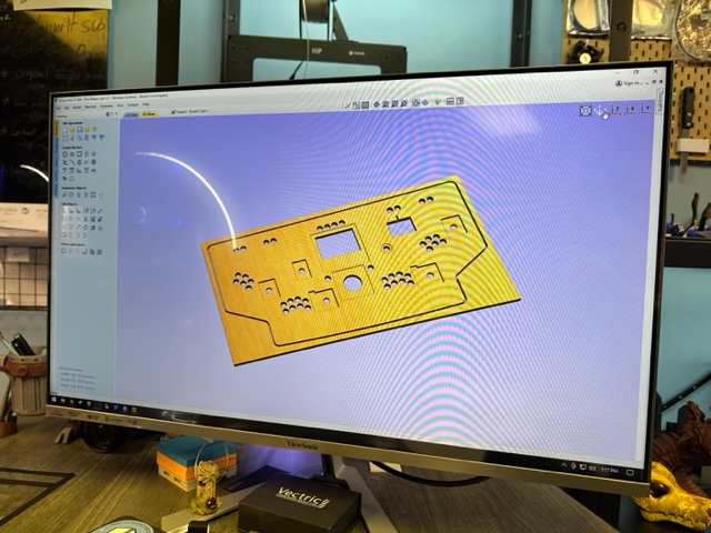
We talked about the next steps and went home.
Plywood Results
Several weeks later when everything was done, we returned to pick up the cut plywood pieces and bring them home.
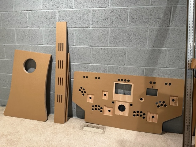
All the cuts looked fantastic and it was exactly as we wanted. I spent some time inserting all of the controls and other components into the holes to make sure they fit properly.
Fixing Mistakes
I did come across three relatively minor issues during my testing that were all my fault, but could be easily fixed with a Dremel tool.
First, there are several places where 2” flexible desk grommets were meant to be inserted, but the holes were slightly too small. I had measured the grommets incorrectly when I put my design together.
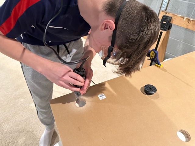
Using a rotary sandpaper bit on the Dremel, we slightly increased the size of each grommet hole until they fit.
Second, the Ultimarc spinner hole was also slightly too small. I didn’t account for a wire that runs up the side of it. Again, we were able to use the Dremel to widen the hole a bit to make sure it fits.
And third, the routed area to the right and the left of the 7” display needed about another 1-2mm of routing for the display’s brackets to sit properly on the routed area. My mistake, but fixed with the Dremel.
For all the things that could have gone wrong with this, I’m thankful that those were the only problems!
Acrylic Issues
Nick had let me know that they had an issue cutting the control panel top acrylic and the material was not going to be useable. It turns out that there are a couple types of acrylic and the one found at Menards is an extruded acrylic, instead of a cast acrylic. CNC machines only work well with cast acrylics.
They were able to get a similar cast acrylic sheet so that the cutting work could be completed.
Summary
Woohoo! We now have all the materials needed to get to work on assembling the pedestal.
In the next post, we’ll take a slight detour to work on graphics that will be printed on vinyl and eventually applied on some of the plywood boards.
