The control panel surface is a large 4’ x 2’ area and needs a box frame to house all of the controls and wires. A large cabinet needs to be constructed underneath the control panel box to hold the PC and provide storage for accessories like light guns. The pedestal will be mounted on casters so that it can be moved around easily on hard floors. I’ll use a 3-D design application to virtually model all the wood pieces for the cabinet.
The previous post walked through all the controls and devices we’ll be using on the control panel, and discussed using Affinity Designer to design the control panel layout.
Goals
The control panel surface is planned, so let’s move onto the next step of planning out the rest of the pedestal. I’ll list some goals of the project.
- Control box that is under the main control panel board will be 5” tall.
- It will have a couple USB extenders on the front face.
- It will have a pinball plunger button on the front face, along with pinball flipper and tilt buttons on a couple side faces.
- The back of the control box will have air vents for circulation.
- The control box will be tilted down towards the front at roughly a 5 degree angle.
- The cabinet underneath will have a single door.
- The cabinet will have a shelf in the middle and the PC will rest on the shelf.
- The sides of the cabinets will have two large fan holes to allow for active airflow across the PC.
- There will be holes between various panels to allow for wires to run within the cabinet and up to the control panel.
- The rear of the cabinet will have a USB extender, HDMI out, power input, and a grommet to run any future additional wires.
- Casters will be mounted on the bottom of the cabinet.
- The entire pedestal will be about 40” off the ground.
That’s a lofty list, but with some creative design, we’ll make it happen!
SketchUp
I have used SketchUp for many years in various projects, so when it came time to model the pedestal in three dimensions, this was the first app I went to. I find it to be the easiest app of its type for building 3-D models. You simply create shapes, set their dimensions, make groups, drag things around to various snap points, etc. It’s all intuitive.
The version I used is a classic desktop app that is technically no longer supported. They now offer an online subscription-based option that is probably more powerful, and I believe they have a free version of this online version as well. But for my needs, I stuck with the old app that I’m familiar with.
Control Panel Box
I started by modeling the control panel top again. I used the same dimensions that I have used in Affinity Designer. You may be asking, why are you doing this again in another app? I suppose I didn’t have to model all the controls in SketchUp for this project, but it was fun to add them for a realistic 3-D look at my expected result, and I’m a glutton for punishment.
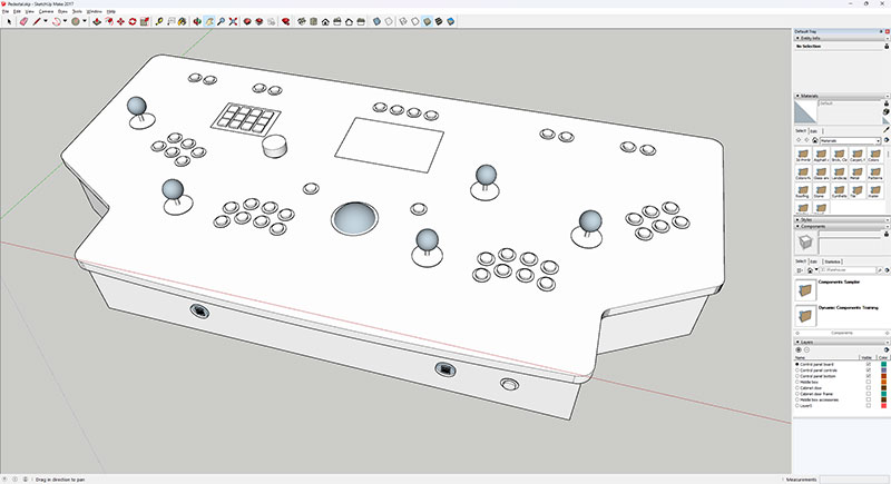
Next I added the 5” tall side pieces vertically underneath the control panel top. I added a couple USB extenders and a pinball plunger button.
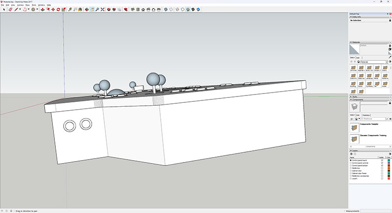
The side pieces closest to the front both have two pinball buttons on them for flipper and tilt.
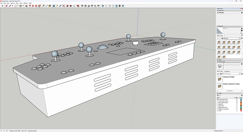
The rear of the control panel box has vents in it so that any hot air can escape and cool air can circulate in. The electronics in the control panel box itself should generate minimal heat, so no active venting will be used here.
Cabinet
The front of the pedestal’s cabinet is a large wood piece where I’ll apply artwork.
Artwork will also be applied to the sides of the cabinet, which have a slight slant along their top edges. This allows the control panel box to be mounted at a 5 degree angle downward towards the front.
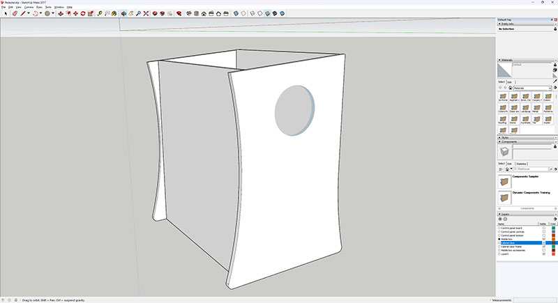
A large hole in each side wood piece will house a 200mm fan, with one side drawing air in and the other pushing air out.
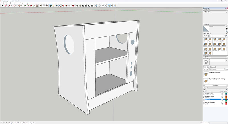
There will be two shelves in the interior of the cabinet. The PC will rest on the upper shelf with the fans actively pushing fresh air across it. The lower shelf will be used more for storage, such as for the light guns. The rear right side has holes for all the external electronic hookups.
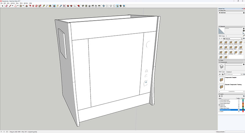
A rear cabinet door will cover the opening to the interior, while fan grills will cover the fan holes.
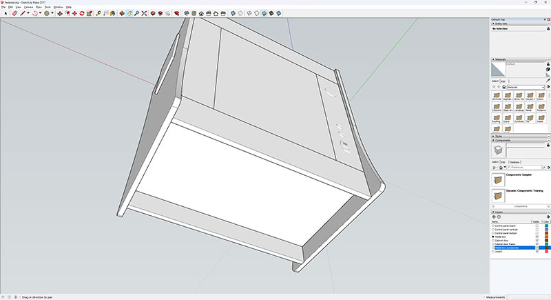
Casters will be be mounted underneath the cabinet, allowing it to move freely across hard surfaces.
Summary
When you combine everything together, you end up with this beautiful pedestal:
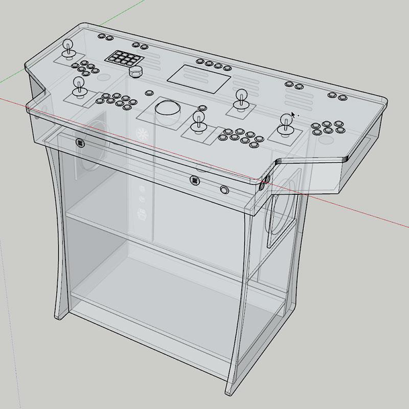
The great thing about having a 3-D model of the pedestal, beyond having a realistic visualization of the desired result, is that it’s now relatively easy to get any measurements I need for any wood pieces.
In the next post, we’ll plan how we can slice up plywood boards to get all the pieces we need, and then will obtain the plywood material, cut it up, and prepare it for taking to a vendor with a CNC machine.
